Reliable Pipelines for a More Sustainable Tomorrow

PIPE SOLUTIONS
PIPE SOLUTIONS
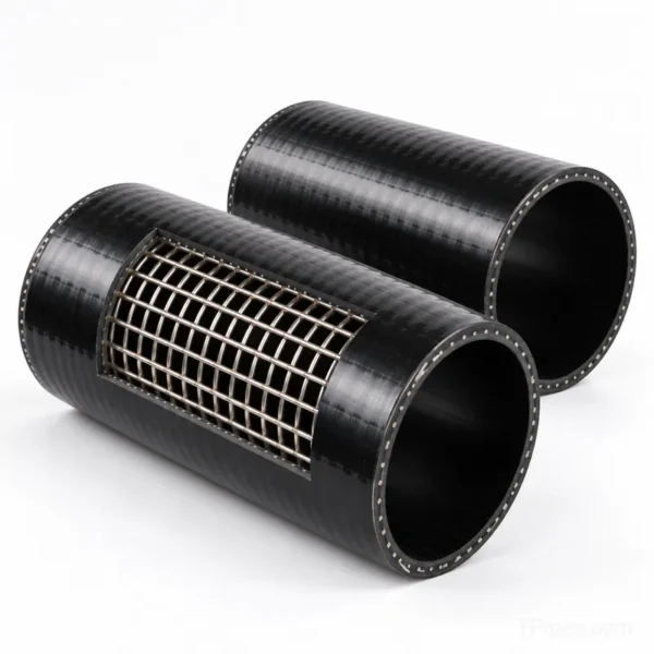
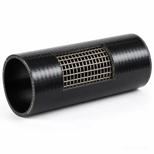
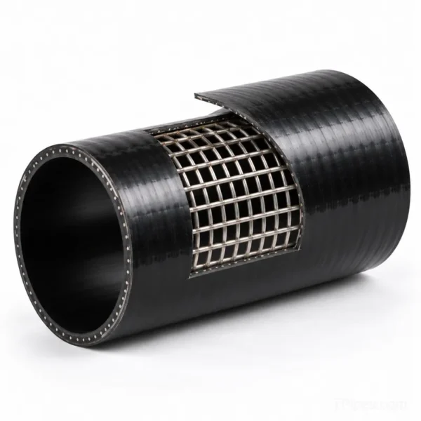
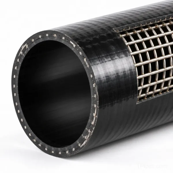
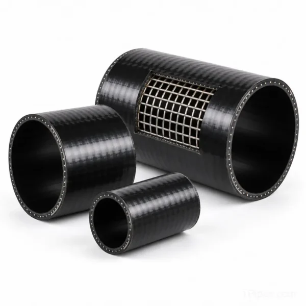
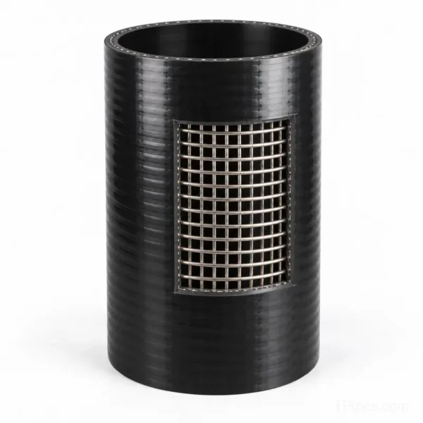
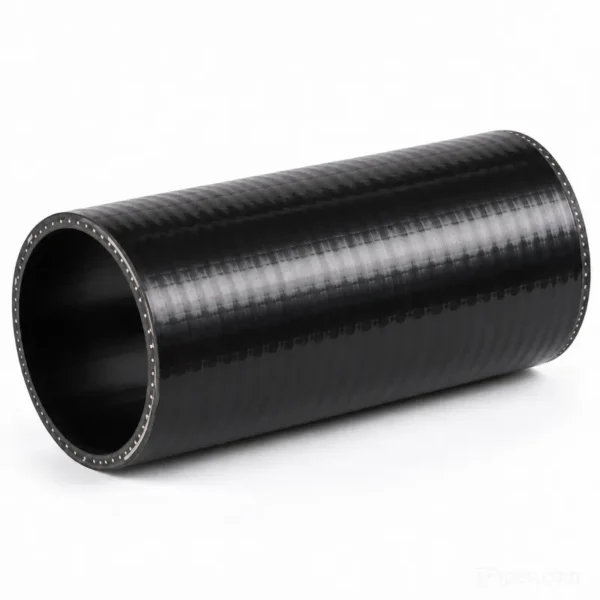
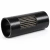
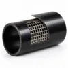
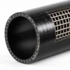
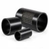
Steel Skeleton PE Composite Pipe for Water & Industry
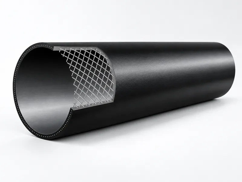
Steel Skeleton Reinforced PE Composite Pipe combines a welded low-carbon steel-wire reinforcing skeleton with polyethylene layers to create a composite pipeline for selected industrial fluid transportation applications.
The technical brochure lists nominal outside diameters from DN75 to DN630, with application-specific pressure classes for water, oil, mixed fluids and designated gas-service products. The composite structure is designed to combine the corrosion resistance of polyethylene with enhanced mechanical strength, dimensional stability and impact resistance.
Available specifications, operating pressure, temperature limits, material grade and compatible fittings should be confirmed against the project requirements and applicable standards before ordering.
Factory Direct Supply
Competitive price and stable quality
OEM / Custom
Tailored to project requirements
Global Export
Serving 100+ countries
Fast Response
Professional engineering support
Description
Steel Skeleton PE Composite Pipe
Steel skeleton PE composite pipe is a reinforced polyethylene pipeline that combines a welded steel-wire skeleton with polyethylene layers. This composite structure is designed to combine the corrosion resistance of polyethylene with enhanced mechanical strength, dimensional stability and impact resistance for selected industrial and infrastructure pipeline applications.
TPipes supplies steel skeleton PE composite pipe for project-specific applications, with nominal outside diameters listed from DN75 to DN630 in the supplied technical brochure. Available pressure ratings, material grades, operating temperatures and compatible fittings depend on the selected specification and intended service.
Composite Structure and Manufacturing Process
The pipe consists of a steel-wire reinforcing skeleton embedded within polyethylene material. According to the supplied Qinyi product brochure, the steel reinforcement uses ordinary low-carbon steel wire, while the polymer material is selected according to the intended service. The brochure identifies high-density polyethylene (HDPE) pipe-grade resin for general applications and medium-density polyethylene (MDPE) pipe-grade resin for designated gas-service products.
The manufacturing process includes steel-wire feeding, polyethylene extrusion, skeleton forming and composite sizing, cooling, haul-off, cutting and finishing. Integrating the reinforcing structure and polymer material during production helps create a composite pipe with consistent geometry and a balanced combination of rigidity and flexibility.
Key Features and Performance Advantages
- Corrosion resistance: Polyethylene provides resistance to many corrosive environments when the selected material is chemically compatible with the conveyed medium.
- Reduced scaling: The smooth polymer inner surface helps limit scale accumulation under suitable operating conditions.
- Enhanced mechanical strength: The steel-wire skeleton contributes to structural strength and resistance to deformation.
- Creep resistance: The composite structure is designed to improve long-term mechanical performance compared with an otherwise comparable unreinforced polymer structure.
- Impact resistance and dimensional stability: The steel-and-polymer construction combines rigidity with a degree of flexibility.
- Low thermal conductivity: The supplied brochure lists a thermal conductivity value of 0.43 W/(m·K).
- Low thermal expansion: The reinforced structure is designed to limit dimensional changes caused by temperature variation.
- Metal reinforcement detectability: The steel skeleton may assist pipe locating, subject to the detection equipment and installation conditions.
Typical Applications
Applications identified in the supplied product brochure include:
- Water supply and selected municipal infrastructure pipelines.
- Oil transportation and mixed-fluid transportation.
- Wastewater and industrial fluid conveyance.
- Designated gas transportation systems using an appropriate material grade and approved pressure rating.
- Selected corrosive-medium transportation applications following chemical compatibility assessment.
- Fire-protection or drinking-water applications only when the specific product, fittings and approvals satisfy the relevant project and regulatory requirements.
Application suitability must be evaluated against the conveyed medium, concentration, operating temperature, pressure, product grade, jointing system and applicable local requirements. The application list is not a blanket approval for every service.
Nominal Outside Diameter and Pressure Specifications
The supplied brochure contains a nominal outside-diameter series from DN75 to DN630. It lists nominal pressure classes of 1.0, 1.6, 2.0, 2.5 and 4.0 MPa for water, oil and mixed-fluid transportation, and 0.4 and 0.8 MPa for designated gas-service products. Availability varies by diameter and service category.
Nominal Wall Thickness for Water, Oil and Mixed Fluids
The following values are transcribed from the supplied technical chart. Wall thickness is expressed in millimetres; the notation in parentheses indicates the listed upper and lower tolerance in millimetres.
| DN (mm) | OD Tolerance | 1.0 MPa | 1.6 MPa | 2.0 MPa | 2.5 MPa | 4.0 MPa |
|---|---|---|---|---|---|---|
| 75 | +0.7/0 | — | — | — | 9 (+1.5/0) | 9 (+1.5/0) |
| 90 | +0.8/0 | — | — | — | 9 (+1.5/0) | 9 (+1.5/0) |
| 110 | +1.0/0 | — | 9 (+1.5/0) | 9 (+1.5/0) | 9 (+1.5/0) | 9 (+1.5/0) |
| 125 | +1.1/0 | — | 8.5 (+1.5/0) | 9 (+1.5/0) | 9 (+1.5/0) | 9 (+1.5/0) |
| 140 | +1.3/0 | — | 9.5 (+1.5/0) | 10 (+1.5/0) | 10 (+1.5/0) | 10 (+1.5/0) |
| 160 | +1.5/0 | — | 11 (+1.5/0) | 11.5 (+1.5/0) | 11.5 (+1.5/0) | 12 (+1.8/0) |
| 200 | +1.8/0 | — | 11.5 (+1.8/0) | 12 (+1.8/0) | 12 (+1.8/0) | 12 (+1.8/0) |
| 225 | +2.0/0 | — | 12 (+1.9/0) | 12.5 (+2/0) | 12.5 (+2/0) | 12.5 (+2/0) |
| 250 | +2.5/0 | 12 (+2/0) | 12 (+2/0) | 12.5 (+2/0) | 12.5 (+2/0) | 12.5 (+2/0) |
| 315 | +2.8/0 | 12 (+2/0) | 12 (+2/0) | 12.5 (+2/0) | 12.5 (+2/0) | 12.5 (+2/0) |
| 355 | +3.2/0 | 12 (+2/0) | 12 (+2/0) | 12.5 (+2/0) | 12.5 (+2/0) | — |
| 400 | +3.6/0 | 14.5 (+2.4/0) | 14.5 (+2.4/0) | 15.5 (+2.5/0) | 15.5 (+2.5/0) | — |
| 450 | +4.1/0 | 14.5 (+2.4/0) | 14.5 (+2.4/0) | 15.5 (+2.5/0) | 15.5 (+2.5/0) | — |
| 500 | +4.5/0 | 15.5 (+2.5/0) | 15.5 (+2.5/0) | 16 (+2.6/0) | 16 (+2.6/0) | — |
| 560 | +5.0/0 | 15.5 (+2.5/0) | 15.5 (+2.5/0) | 16 (+2.6/0) | — | — |
| 630 | +5.7/0 | 19 (+2.5/0) | 19 (+3/0) | 20 (+3.5/0) | — | — |
Nominal Wall Thickness for Designated Gas-Service Products
| DN (mm) | OD Tolerance | 0.8 MPa | 0.4 MPa |
|---|---|---|---|
| 75 | +0.7/0 | 9 (+1.5/0) | 8.5 (+1.5/0) |
| 90 | +0.8/0 | 9 (+1.5/0) | 8.5 (+1.5/0) |
| 110 | +1.0/0 | 9 (+1.5/0) | 8.5 (+1.5/0) |
| 125 | +1.1/0 | 9 (+1.5/0) | 8.5 (+1.5/0) |
| 140 | +1.3/0 | 10 (+1.5/0) | 9.5 (+1.5/0) |
| 160 | +1.5/0 | 12 (+1.8/0) | 11 (+1.5/0) |
| 200 | +1.8/0 | 12 (+1.8/0) | 11.5 (+1.5/0) |
| 225 | +2.0/0 | 12.5 (+2/0) | 12 (+1.8/0) |
| 250 | +2.5/0 | 12.5 (+2/0) | 12 (+1.8/0) |
| 315 | +2.8/0 | 12.5 (+2/0) | 12 (+1.8/0) |
| 355 | +3.2/0 | 12.5 (+2/0) | 12 (+1.8/0) |
| 400 | +3.6/0 | 14.5 (+2.4/0) | 14.5 (+2.4/0) |
| 450 | +4.1/0 | 14.5 (+2.4/0) | 14.5 (+2.4/0) |
| 500 | +4.5/0 | 15.5 (+2.5/0) | 15.5 (+2.5/0) |
| 560 | +5.0/0 | 15.5 (+2.5/0) | 15.5 (+2.5/0) |
| 630 | +5.7/0 | 20 (+3.5/0) | 19 (+3.4/0) |
Specification note: These tables reproduce the nominal outside-diameter series in the supplied brochure. The original source should be checked against the current approved product specification before these dimensions are used for procurement or engineering design.
Ring Stiffness, Bending Radius and Support Spacing
The following values are listed in the supplied technical brochure. Final installation design should also consider the pipe specification, temperature, loading conditions, support design and applicable installation requirements.
| Nominal Diameter DN (mm) | Ring Stiffness (kPa) |
|---|---|
| 160 | 47.52 |
| 225 | 21.26 |
| 250 | 16.05 |
| 315 | 9.28 |
| 400 | 7.32 |
| 500 | 5.52 |
| 630 | 4.85 |
| Nominal Outside Diameter | Minimum Bending Radius Listed in Brochure | Suggested Support Spacing Listed in Brochure |
|---|---|---|
| DN75–DN90 | 80D | 2.5 m |
| DN110–DN125 | 80D | 3.0 m |
| DN140–DN160 | 80D | 3.5 m |
| DN200–DN315 | 100D | 4.0 m |
| DN355–DN630 | 110D | 4.5 m |
Here, D represents the nominal outside diameter. These values are reference data from the brochure, not a substitute for project-specific installation calculations.
Operating Temperature and Pressure Derating
The brochure gives a general product operating-temperature range of -40°C to 80°C. Permissible pressure depends on the service, selected material grade and temperature. The following temperature correction factors are reproduced from the supplied brochure for reference.
| Service | Temperature Range (°C) | Pressure Correction Factor |
|---|---|---|
| Water supply | 1 < t ≤ 20 | 1.00 |
| Water supply | 20 < t ≤ 30 | 0.95 |
| Water supply | 30 < t ≤ 40 | 0.90 |
| Water supply | 40 < t ≤ 50 | 0.86 |
| Water supply | 50 < t ≤ 60 | 0.81 |
| Water supply | 60 < t ≤ 70 | 0.76 |
| Water supply | 70 < t ≤ 80 | 0.60 |
| Industrial service | 1 < t ≤ 20 | 1.00 |
| Industrial service | 20 < t ≤ 30 | 0.95 |
| Industrial service | 30 < t ≤ 40 | 0.90 |
| Industrial service | 40 < t ≤ 50 | 0.86 |
| Industrial service | 50 < t ≤ 60 | 0.81 |
| Industrial service | 60 < t ≤ 70 | 0.76 |
| Gas service | -20 < t ≤ 0 | 0.90 |
| Gas service | 0 < t ≤ 20 | 1.00 |
| Gas service | 20 < t ≤ 25 | 0.93 |
| Gas service | 25 < t ≤ 30 | 0.87 |
| Gas service | 30 < t ≤ 35 | 0.80 |
| Gas service | 35 < t ≤ 40 | 0.74 |
These factors should be verified against the applicable current specification before calculating the permitted working pressure. The general temperature range must not be interpreted as approval for every medium or pressure class across the entire range.
Physical and Mechanical Performance
The supplied brochure lists the following test indicators:
- Longitudinal shrinkage after exposure to 110°C for one hour: less than 3%.
- Oxidation induction time at 200°C: greater than 20 minutes.
- Melt mass-flow rate change before and after processing at 190°C under a 5 kg load: less than 20%.
- Short-term hydrostatic testing includes conditions at 20°C for 100 hours and 70°C for 165 hours, with no leakage or rupture as the stated performance criterion.
Test values and acceptance criteria should be checked against the original test documentation and the applicable product standard before being used as contractual guarantees.
Chemical Compatibility
The brochure includes indicative chemical-resistance data at 20°C and 60°C. Examples are summarized below. S means good resistance, L means limited resistance and NS means poor resistance in the source chart.
| Medium | Concentration Listed | 20°C | 60°C |
|---|---|---|---|
| Acetaldehyde | 100% | S | L |
| Gasoline / petroleum hydrocarbons | Not specified | S | L |
| Mercury | 100% | S | S |
| Toluene | 100% | L | NS |
| Sodium hydroxide | 40% | S | S |
| Sulfuric acid | 50% | S | S |
| Sulfuric acid | 98% | S | NS |
| Fuming sulfuric acid | Fuming | NS | NS |
This chart is indicative only. Chemical resistance depends on the exact polymer grade, concentration, temperature, exposure duration, mechanical stress and system design. Confirm compatibility before selecting the pipe for chemical service.
Technical Standards Referenced in the Brochure
The supplied brochure references the following Chinese industry standards:
- CJ/T 123-2016 — Steel Skeleton Reinforced Polyethylene Composite Pipe for Water Supply.
- HG/T 3690-2012 — Industrial Steel Skeleton Reinforced Polyethylene Composite Pipe.
- HG/T 3691-2012 — Industrial Fittings for Steel Skeleton Reinforced Polyethylene Composite Pipe.
- SY/T 6662.1-2012 — Steel Skeleton Reinforced Polyethylene Composite Pipe.
These are references cited in the supplied brochure, not a representation that every product configuration currently holds every listed certification. Confirm the applicable edition, product scope, test reports and market-specific approvals before procurement.
Request a Quote for Your Pipeline Project
TPipes can review your project requirements to help identify an appropriate pipe specification. Please provide the nominal diameter, conveyed medium, operating temperature, working pressure, required quantity, project location, applicable standard and any required fittings or connection details.
APPLICATIONS
Applications & Connection Methods
Reliable performance in demanding environments. Widely used in water supply. gas, chemical, mining, municpal and other pipeline projects
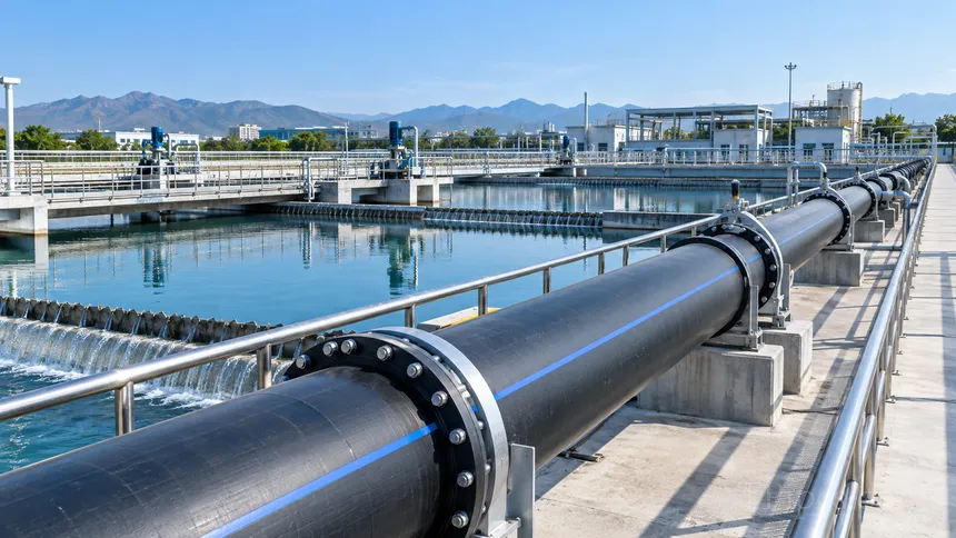
Water Supply
Pipeline solutions for water transmission and distribution projects, subject to required pressure, specification and installation conditions.Best For:
Municipal water networks, industrial water systems and long-distance water transmission.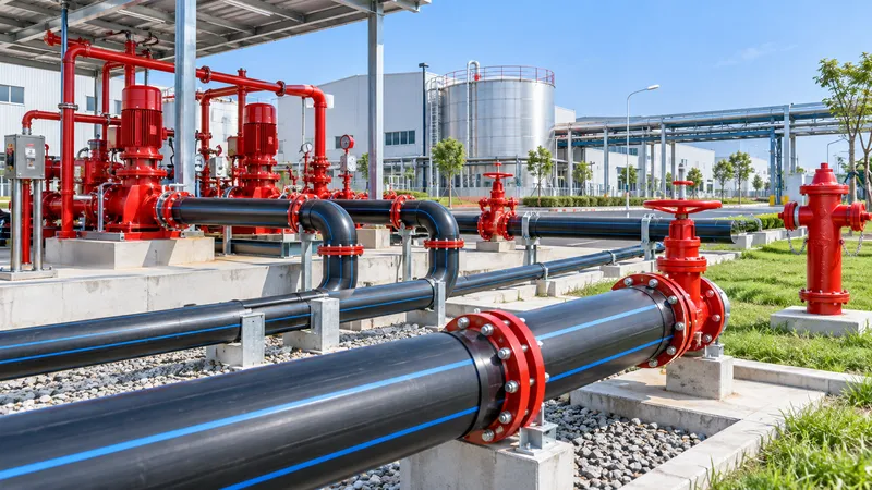
Fire Protection Pipeline
Durable reinforced polyethylene pipeline solutions for fire water supply systems, providing stable performance for hydrant, sprinkler and firefighting pipeline networks.Best For:
Industrial parks, warehouses, commercial buildings, municipal fire protection networks and other projects requiring reliable fire water delivery.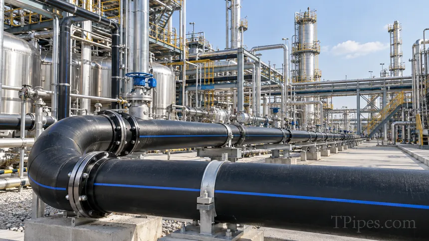
Chemical & Industrial Pipeline
Suitable product configurations may be selected for industrial fluid transport according to chemical compatibility and operating conditions.Best For:
Industrial process pipelines and selected chemical fluid transport applications.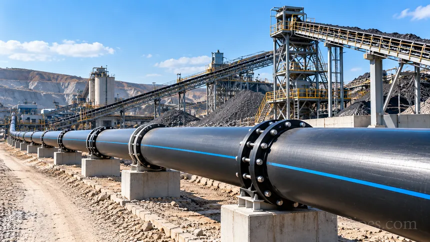
Mining & Municipal Infrastructure
Reinforced pipeline solutions for demanding infrastructure environments,subject to medium characteristics and project design requirements.Best For:
Mining water systems, municipal engineering and selected industrial infrastructure projects.CONNECTION METHODS
Reliable Connections for Long-Term Use
Select the appropriate connection method according to pipe specification, operating pressure, installation conditions and connected equipment.
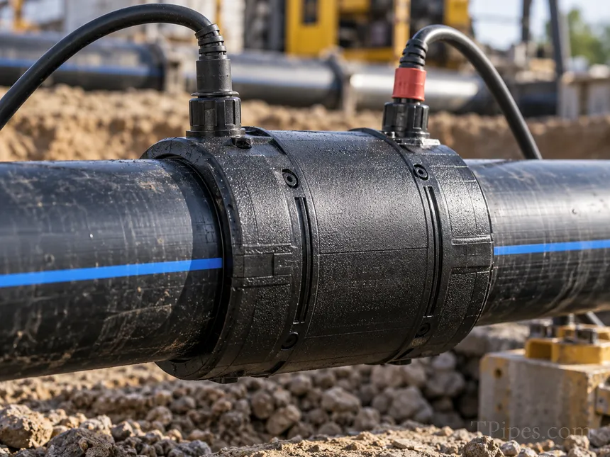
Electrofusion Connection
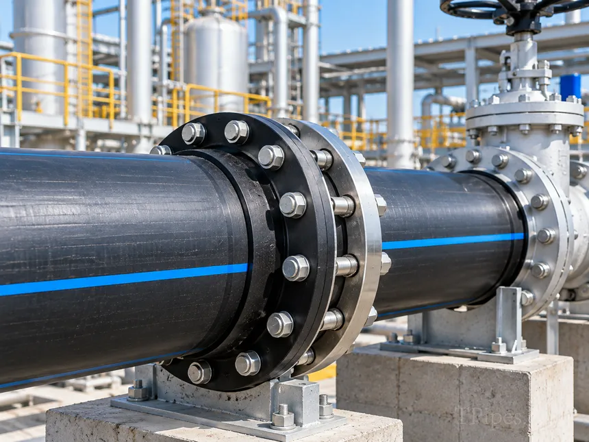
Flange Connection
INSTALLATION PROCESS
Simple Installation in 3 Steps
A simplified overview of the installation process.
Actual procedures should follow the applicable product specification and project requirements.
Actual procedures should follow the applicable product specification and project requirements.
1
Prepare
Cut the pipe to the required length and clean the connection area.
2
Connect
Use electrofusion or flange connection according to the project requirements.
3
Inspect
Checkthe connection quality, complete testing, and put into operation.
Not sure which connection method is right for your project?
Send us your pipe size, pressure, application and installation conditions.
Our team can help review the connection requirements.
Our team can help review the connection requirements.
OUR STRENGTH
Manufacturing Strength & Quality Assurance
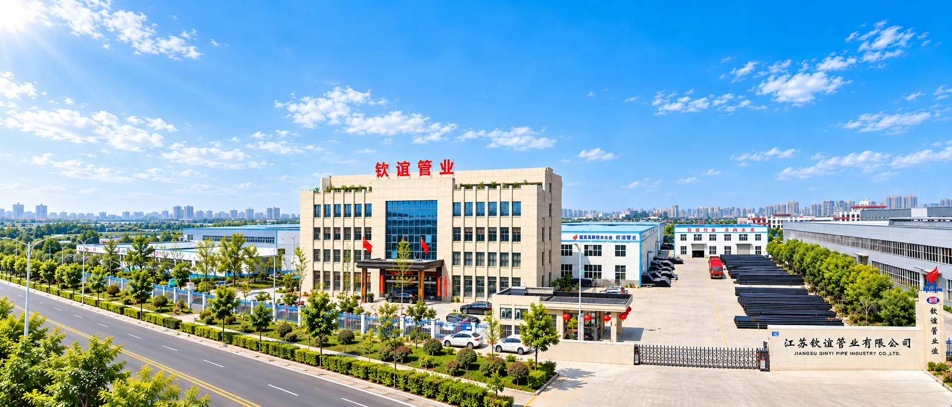
From raw materials and production processes to finished-pipe inspection,TPipes applies controlled manufacturing procedures to support consistent product quality and reliable project supply.
100
Production Base
0
Production Capability
0
Manufacturing Experience
0
Export Markets
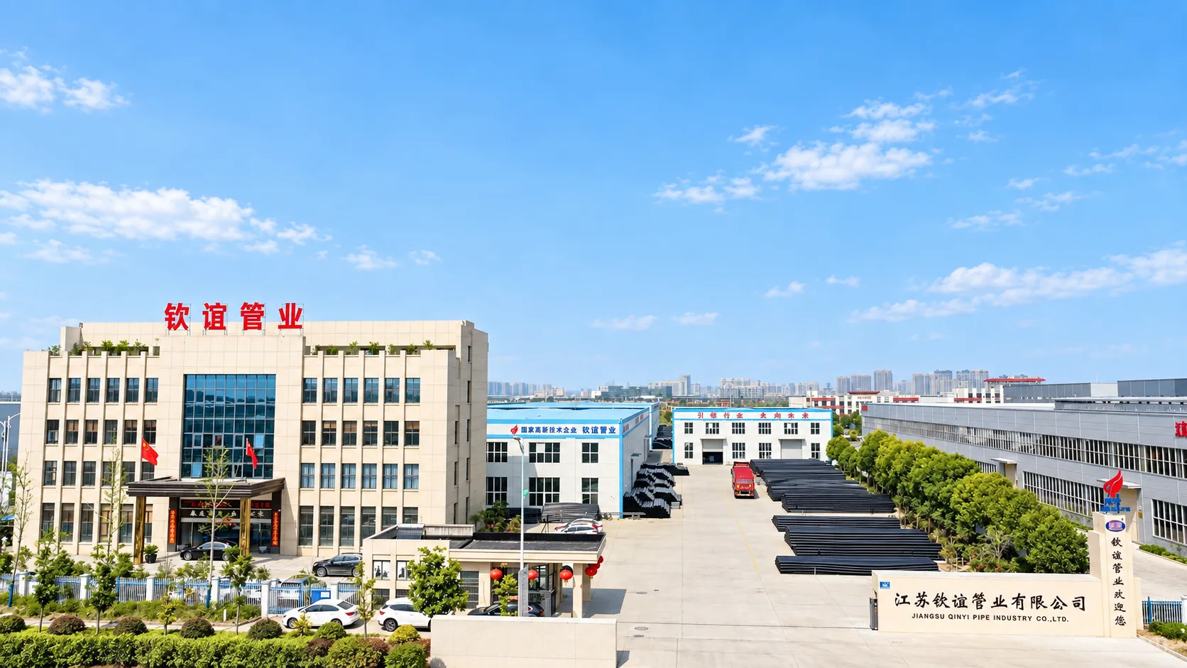
TPipes pipe manufacturing facility
PROFESSIONAL
MANUFACTURER FOR
A MORE RELIABLE WORLD
MANUFACTURER FOR
A MORE RELIABLE WORLD
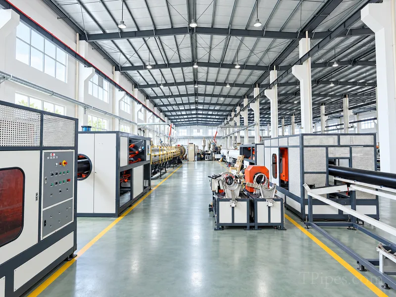
Production Workshop
BuDedicated production areas support organized pipe manufacturing and material handling.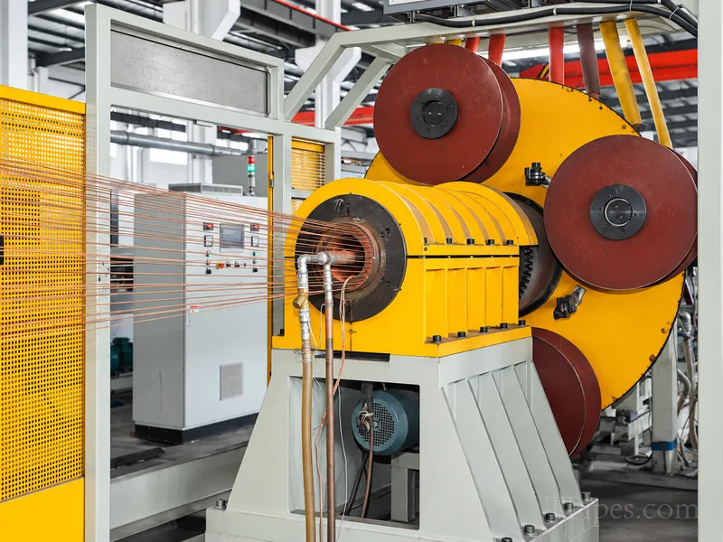
Production Equipment
Specialized equipment supports reinforcement forming, PE processing and pipe production.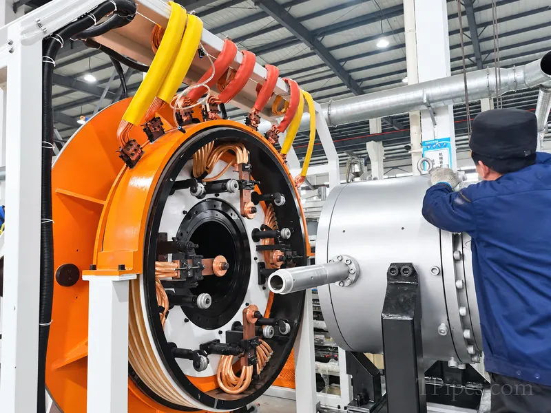
Controlled Manufacturing Process
Key production stages are managed according to product specifications and manufacturing requirements.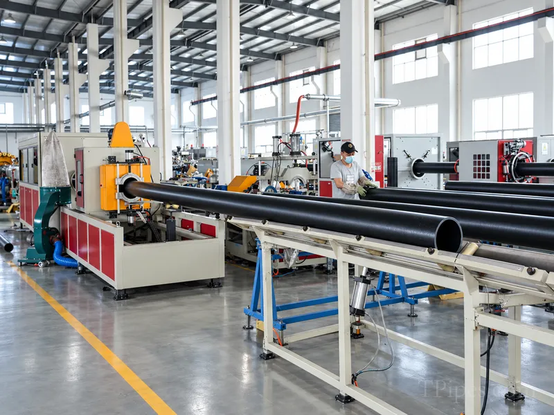
Quality Inspection
Finished products are inspected according to applicable product and project requirements.FAQ
Frequently Asked Questions
Find quick answers to common questions about this product, including specifications, applications, connection methods
and project requirements.
and project requirements.
What Is a Steel Skeleton Reinforced PE Composite Pipe?
It is a composite pipeline made by integrating a welded steel-wire reinforcing skeleton with thermoplastic polyethylene layers. The steel reinforcement contributes to mechanical strength and dimensional stability, while the polyethylene provides a smooth internal surface and resistance to many corrosive environments.
What Materials Are Used in Steel Skeleton PE Composite Pipes?
According to the supplied brochure, the reinforcing structure uses ordinary low-carbon steel wire. The polymer material is selected for the intended service, with HDPE pipe-grade resin identified for general applications and MDPE pipe-grade resin for designated gas-service products. The exact material grade should be confirmed for each order.
What Diameters and Pressure Ratings Are Available?
The supplied nominal outside-diameter table covers DN75 to DN630. It lists pressure classes of 1.0, 1.6, 2.0, 2.5 and 4.0 MPa for water, oil and mixed fluids, and 0.4 and 0.8 MPa for designated gas-service products. Availability varies by diameter, material grade and service. Request the current dimensional datasheet for the selected specification.
What Is the Operating Temperature Range?
The brochure lists a general operating-temperature range of -40°C to 80°C. The allowable working pressure can decrease as temperature increases, and the permitted range differs by application. Confirm the applicable temperature correction factor and service-specific limits before final selection.
Which Applications Are Suitable for This Composite Pipe?
The brochure identifies water supply, oil transportation, mixed-fluid transportation, wastewater and selected industrial services. Gas transportation, drinking water, fire-protection systems and corrosive chemical service require verification of the exact product grade, pressure class, fittings, chemical compatibility and applicable approvals.
Is Steel Skeleton PE Composite Pipe Resistant to Chemical Corrosion?
The polyethylene layers provide resistance to many chemical environments, but compatibility is not universal. Concentration, temperature, exposure time and mechanical stress can affect performance. Provide the chemical name, concentration and operating conditions so that the proposed pipe specification can be checked before ordering.
Which Standards Apply to Steel Skeleton PE Composite Pipe?
The supplied brochure references CJ/T 123-2016, HG/T 3690-2012, HG/T 3691-2012 and SY/T 6662.1-2012. The applicable standard depends on the product and application. Current editions, certification status, test documentation and local regulatory requirements should be verified for the intended market.
What Information Is Needed to Request a Quote?
Please provide the nominal diameter, required length and quantity, conveyed medium, working pressure, operating temperature, project country, applicable standard and any required fittings or connection details. These details help determine the appropriate product specification and whether additional technical verification is required.
WE ARE HERE TO HELP
Need Technical Support?
Get support with product selection, specifications, applications and project requirements. Our team will respond within 24 hours.
Product Support
Project AssistanceTechnical Consultation
Specification SupportProfessional Technical Support
Project-Specific Solutions
Global Project Experience
Fast Response Within 24 Hours
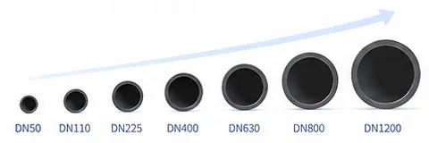
Available Sizes
Wide range of diameters to meet diverse project needs.
Related Products
Related Products for Complete Pipeline Solutions
Explore compatible pipe systems and related product options for different pipeline applications and project requirements.
Steel Wire Mesh Reinforced PE Composite Pipe
High-strength composite pipe with steel wire mesh and PE coating, offering excellent pressure resistance and durability.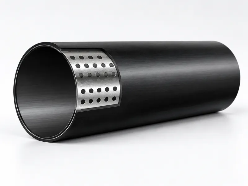
Perforated Steel Strip PE Composite Pipe
Composite pipe with perforated steel strip structure, combining strength and flexibilityfor a wide range of applications.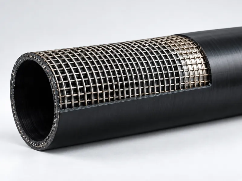
Steel Skeleton PE Composite Pipe
Steel skeleton PE composite pipe combines a reinforced structural layer with polyethylene for demanding industrial and infrastructure pipeline applications. Explore available pipe products, specifications and project solutions.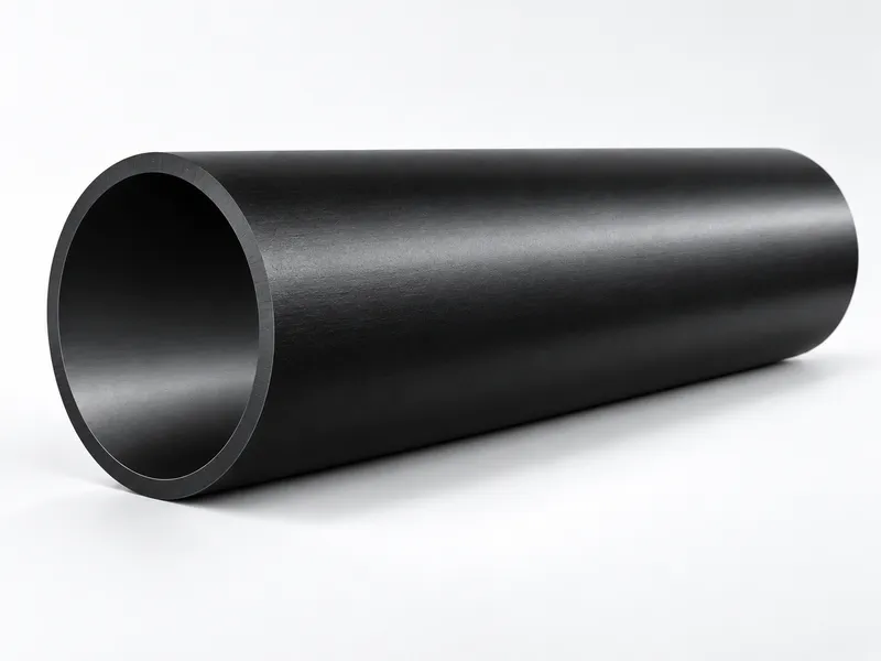
PE / HDPE Pipe
Explore TPipes PE and HDPE pipe products for water supply, municipal infrastructure, industrial pipelines and other project applications. Contact us for product selection and project requirements.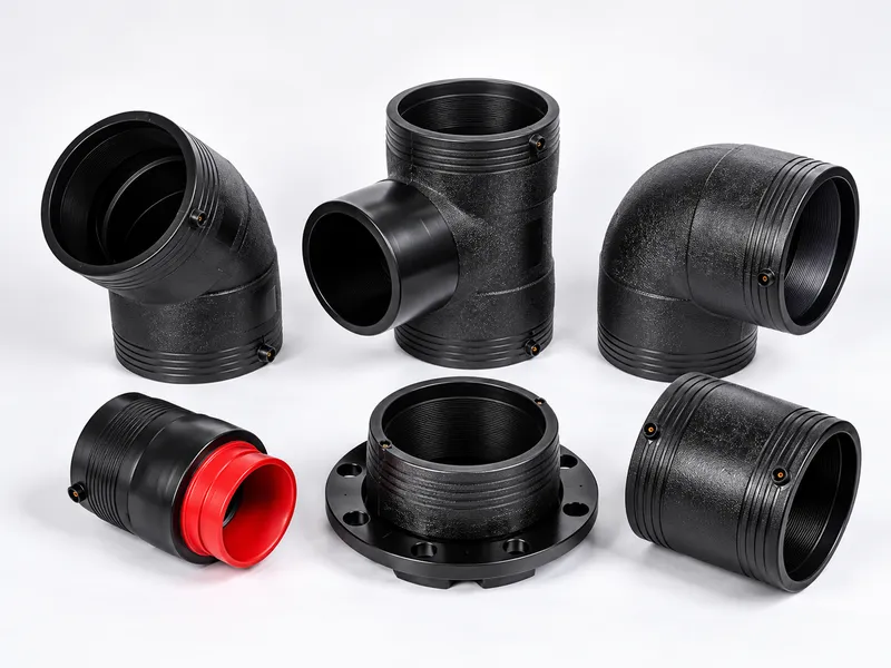
Pipe Fittings
A full range of PE pipe fittings, includingelbows, tees, reducers, flanges and more,ensuring reliable and efficient pipelineconnections.Why Choose TPipes
Reliable pipe solutions, manufacturing support and responsive communication for industrial and infrastructure projects.
Factory Direct Supply
Direct communication with the manufacturing team.Custom Specifications
Solutions evaluated according to your project requirements.Quality Control
Manufacturing and inspection processes focused on product consistency.Export Coordination
Documentation and logistics coordination for international orders.Responsive RFQ Support
Assistance with product selection, specifications and quotations.Talk to a Sales Engineer
Get support with product selection, specifications and connection requirements for your project.Your information is safe with us.